Correction Factors For Cable Calculations

The rated current carrying capacity of a cable (as indicated in appendix 4 BS7671) is quoted for a range of installation methods. These are primarily based on the ability of the cable to dissipate any heat generated internally due to current flow.
|
|

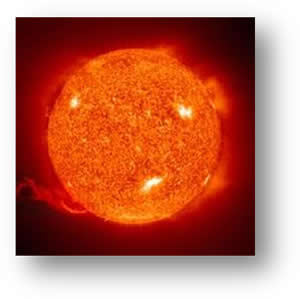
Ambient temperature – The standard or reference temperature for the installation of cables is 30oC. If cables are installed in conditions where the ambient temperature is in excess of this then a correction factor must be able when calculating the required cable cross section. A table of correction factors for ambient temperature may be viewed in BS7671. The symbol for the Correction factor for ambient temperature is Ca.
 Thermal Insulation – If a cable, through any part of its run, passes completely through thermal insulation this can greatly impede its ability to dissipate heat generated through current flow. Therefore regulation 523.7 identifies corrections to be made for this situation. The symbol for correction factor for thermal insulation is Ci.

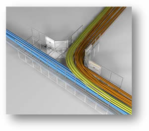
Grouping – Where cables are run in contact with each other heat dissipation is made more difficult as cables can impose an external heating effect on each other. This must again be accounted for in determining the current carrying capacity for a cable. Table 4C1 of BS7671 gives values for cables that are grouped and touching. The symbol for correction factor for cable grouping is Cg.

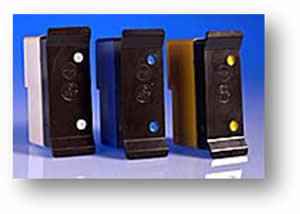
Protective Device – Where the circuit protective device is a semi-enclosed fuse to BS3036 a correction factor must be applied to make up for potential hazards that may otherwise arise under overload conditions. The symbol for correction factor for a BS3036 fuse is Cf and it has a value of 0.725.
Therefore the cable size is selected based on the size of the device protecting it, having considered the above…
Where It ≥ In/(Ca x Ci x Cg x Cc)
In the absence of any stated or recognised external influences for an installation all correction factors assume a value of 1 (ie: does not change the final figure).
If you are familiar with Cable Calculations the following should be recognisable to you:
Ib = Watts
Volts
In > It
It > In
Vd = mv/A/m x Ib x Length of run
1000
Zs = Ze + (R1 + R2)
So you may wish to attempt these two questions….
Simple Cable Calculations:
Cable Calculation No 1:

Determine:
Ib
In
It
Vd
Zs
Cable Calculation No 2:

Determine:
Ib
In
It
Vd
Zs
Download this page (PDF): Cable Correction


